PERFORMANCE CHARACTERISTICS
OF PATCH CABLES
Conductor material, cable construction, shielding and insulation or cables heathing materials are decisive factors for the signal quality and thus the performance of patch cables in their respective areas of application. For easier identification these classification features have been divided into classes or categories with minimum requirements regarding a cable’s transmission bandwidth, shielding types, circuitry and signal attenuation.
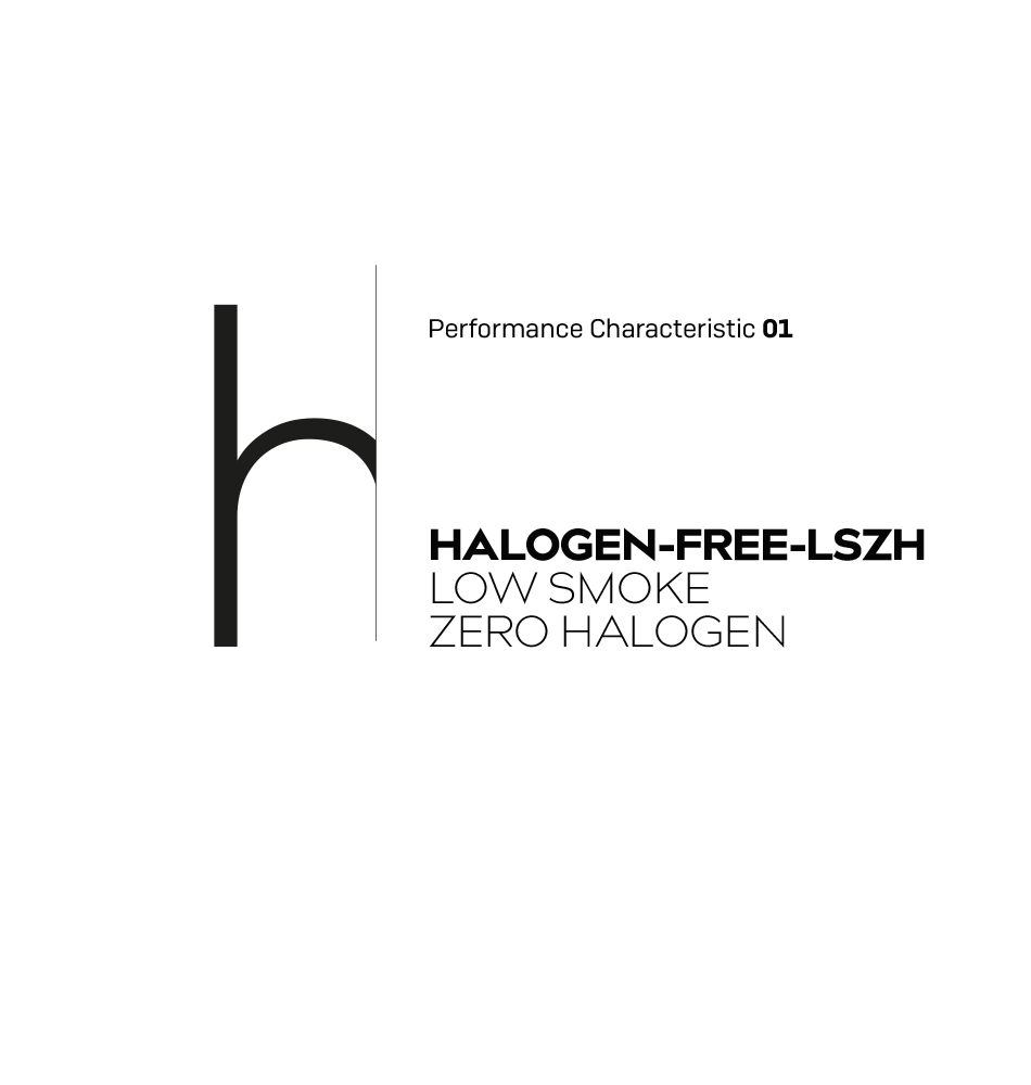
This is a type of cable sheathing and insulation material that emits low levels of smoke during fires and does not contain any halogens (fluorine, chlorine, iodine, bromine) as these release highly toxic gases (e.g. chlorine gas) during combustion. The use of cables from this class is vital,
especially in public spaces.
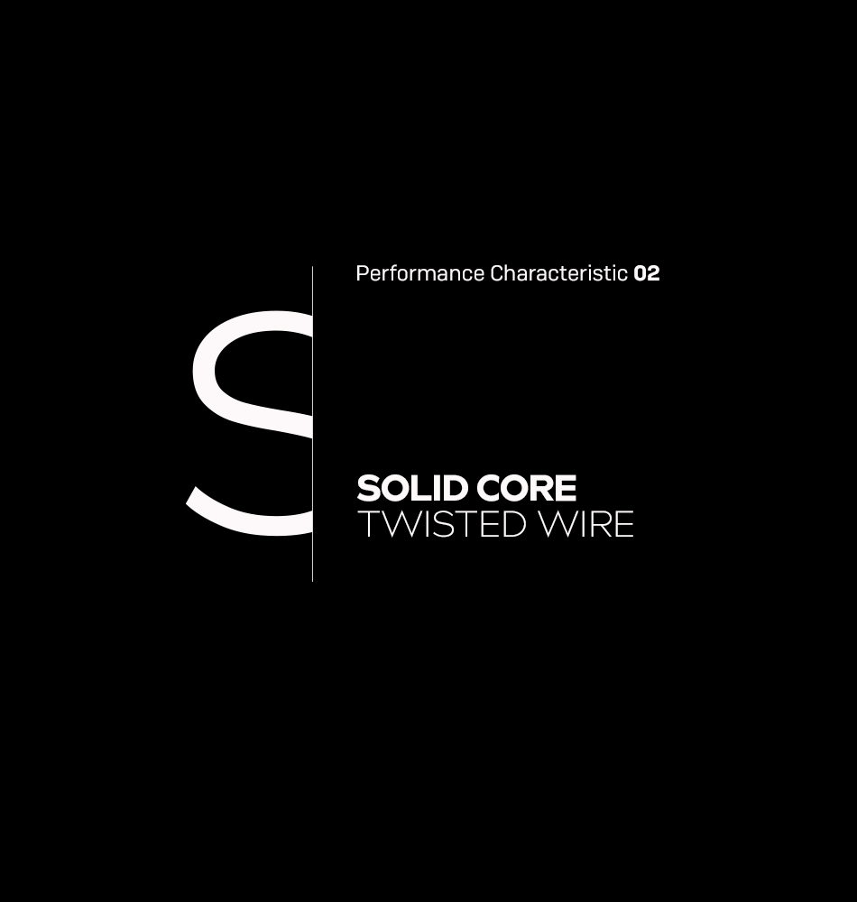
As standard, the conductors of patch cables consist of one strand (thin wire), which is twisted together from several very fine wires, which results in higher flexibility, but unfortunately also a worse electrical conductance compared to solid wires. Certain applications that are specifically dependent on good conductivity (e.g. some extender solutions that use Cat.X cables) therefore require solid-core cables with solid copper cores.
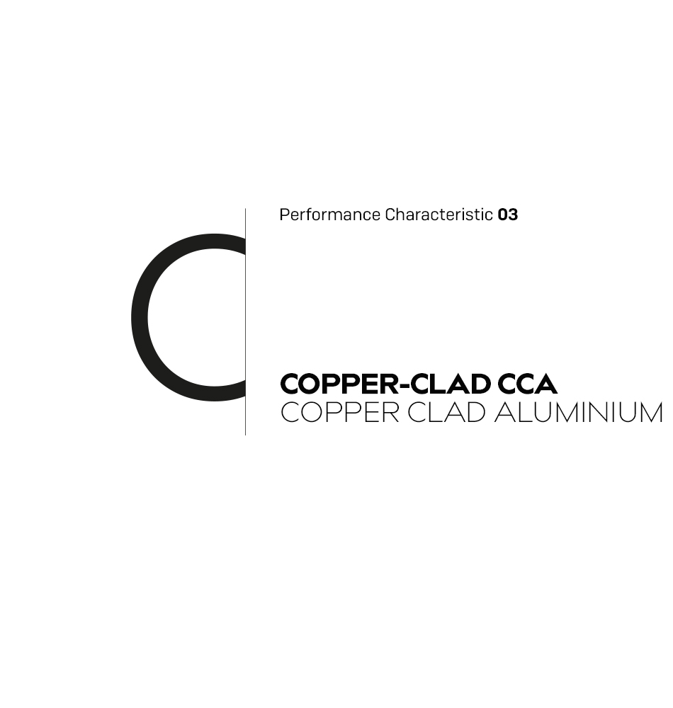
This is a copper clad aluminium conductor material. It makes use of what is known as the “skin effect”, which ensures that at the high transmission frequencies on network cables the signal current flow essentially loads the outer layer of the cable core electrically, while virtually no current flows inside. This means that the cable cores inside can be made of the less conductive but also less expensive, aluminium while the outer layer is made of the more conductive copper. This type of cable is not recommended for PoE application since the PoE power supply (see above) operates with DC voltage (where the “skin effect” does not occur) and therefore increased heat in the cable must be expected because of the poorer electrical conductivity of aluminium.
This is an American coding for wire thicknesses, developed from the number of necessary drawing steps with the production of wires. The higher the AWG value, the thinner the wire. For the copper conductors of AWG cables, values between AWG26 and AWG28 are common.
PATCH CABLES REPRESENT
THE LIFELINES
OF MODERN
COMMUNICATION INFRASTRUCTURE
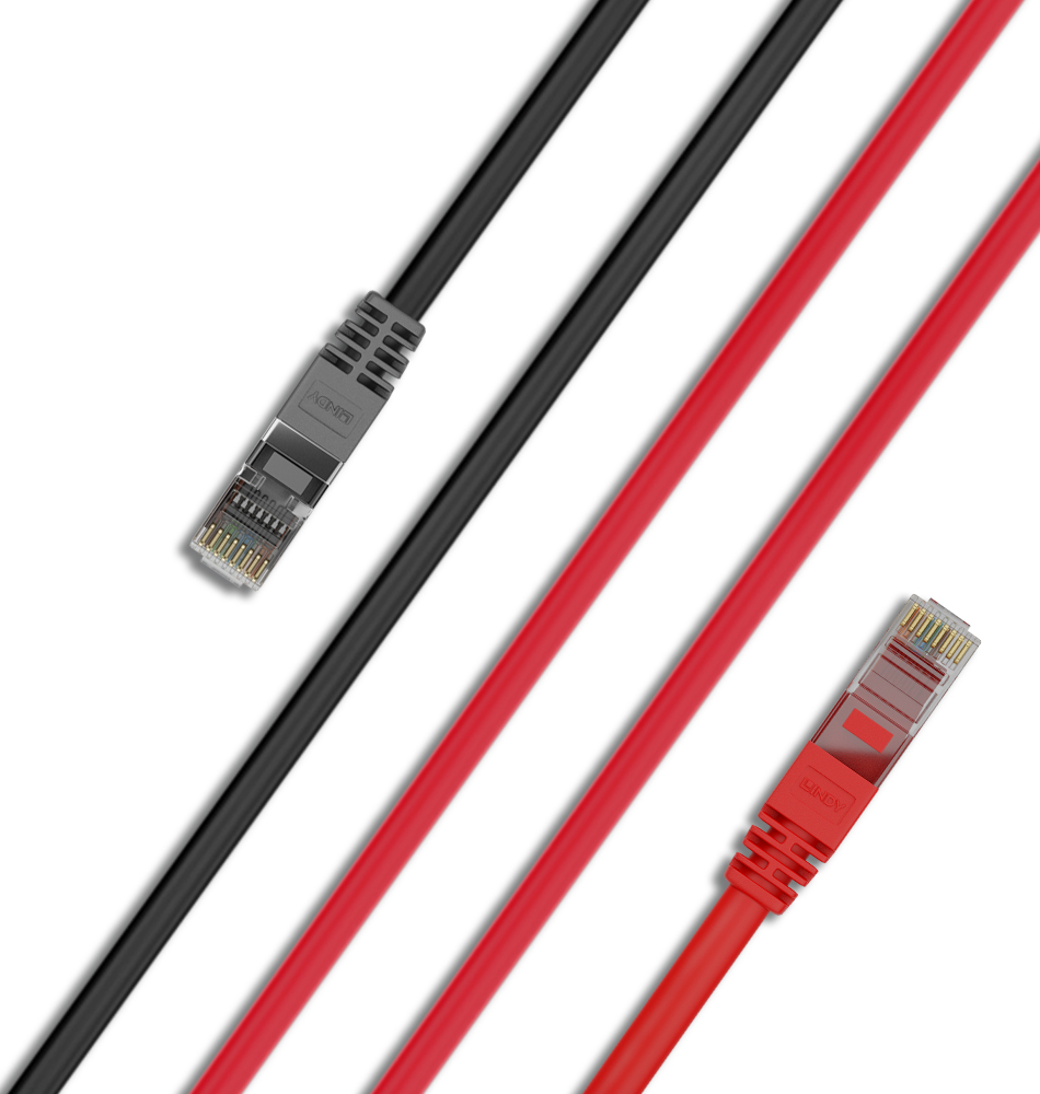

In contrast to the 1:1 wired standard patch cable, crossover cables have a crossed pinout. With these cables, the connection between transmitter and receiver pins is realised by a different wiring of both connectors on a patch cable. This allows two terminals to be connected directly without the need for an intermediate hub or switch. For example, two PCs or a PC and network camera.
Network terminals generally require not only a data connection but also a power supply, usually in the form of a plug-in power supply unit. This can quickly become a problem with remotely placed devices such as WLAN access points or network cameras due to a lack of nearby sockets. The PoE standard not only transmits data but also provides power via the network cable if the switch and terminal device both support PoE.

In standard network operation, the transmitter pin pairs of one device are connected to the receiver pin pairs of the other device in a cable connection using RJ45 connectors. Network devices (hubs, switches, repeaters, routers etc.) and terminal devices (PCs, servers, printers, cameras etc.) are wired differently at their connections by specification, so that connections are possible with standard patch cables which have 1:1 wiring. This means that both connectors have the same pins connected to each other.
These are plastics frequently used as insulation and sheathing materials (usually halogen-free), which exhibit elastic properties at their operating temperature but plastic properties in the event of high heat input, making them ideally suited for the above application.